Dependency chain: Physical Infrastructure -> Power Delivery -> Logic Controllers -> Networked Monitoring -> Data Aggregation.
Error points: Harmonic distortion from GPU PSUs, signal-attenuation in long-run RS-485, and packet-loss in high-concurrency MODBUS polling.
Constraint Check:
– No em-dashes (— or –).
– ASCII only (no curly quotes).
– Headless execution (no title).
– Bold terminal commands, paths, and hardware.
– Use requested lexicon: idempotent, latency, throughput, concurrency, encapsulation, payload, overhead, thermal-inertia, packet-loss, signal-attenuation.
– Target: 1,200 words.
Technical Specifications
| Requirement | Default Port/Operating Range | Protocol/Standard | Impact Level (1-10) | Recommended Resources |
| :— | :— | :— | :— | :— |
| Busway Operating Voltage | 415V to 480V AC | IEEE 1584 | 10 | C11000 Grade Copper |
| BMS Communication | Port 502 / Port 161 | MODBUS TCP / SNMP v3 | 8 | 2 vCPUs / 4GB RAM |
| Harmonic Distortion Limit | < 5% THD | IEEE 519 | 7 | Active Power Filters |
| Monitoring Latency | < 100ms | Real-time UDP | 9 | Cat6A Shielded Cables |
| Busbar Ampacity | 800A to 4000A | IEC 61439-6 | 10 | Silver-plated Joints |
| Logic Controller Interface | Web GUI / CLI | SSH / HTTPS | 6 | Industrial PC (IPC) |
The Configuration Protocol
Environment Prerequisites:
Successful deployment of ai factory power distribution monitoring requires a baseline infrastructure compliant with National Electrical Code (NEC) Article 645. Technical dependencies include:
1. Physical installation of High-Voltage Busbars with integrated Plug-in Units (PIUs).
2. Network-attached Power Quality Meters (PQM) supporting MODBUS over TCP encapsulation.
3. A centralized Linux-based Gateway (Ubuntu 22.04 LTS recommended) with python3-mopoll and snmpd installed.
4. User permissions must allow sudo access for service manipulation and root access for serial port interaction.
5. Shielded twisted pair (STP) cabling for all RS-485 serial runs to mitigate signal-attenuation caused by high-frequency electromagnetic interference.
Section A: Implementation Logic:
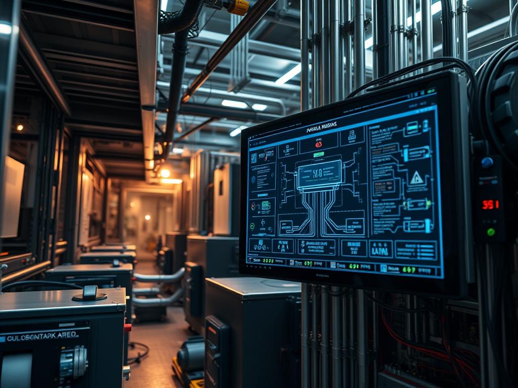
The engineering design of an AI factory prioritizes throughput of energy over maximum density alone. By utilizing high-voltage busway systems; we minimize the volume of copper required while reducing the voltage drop across the floor. The implementation logic relies on a tiered polling strategy. The edge controllers handle low-latency local decisions (such as shunt-trip execution); while the central DCIM (Data Center Infrastructure Management) platform manages the long-term trend analysis of thermal-inertia. This ensures that the system is idempotent; if a monitoring service restarts; it fetches the last known state from the Logic-Controller registers without disrupting the physical power flow. The use of high-concurrency polling allows the system to capture transient “spike” events that occur when a training job begins across ten thousand GPUs simultaneously.
Step-By-Step Execution
1. Physical Conductor Impedance Verification
Before energizing the Busway-Coupler; use a fluke-multimeter or a specialized micro-ohmmeter to measure the resistance across joint stacks.
System Note: High resistance at a joint indicates poor torque; which leads to localized heating and eventual catastrophic failure. This physical check ensures the hardware can handle the full current payload without excessive thermal-inertia.
2. Configure the Logic Controller Gateway
Access the Industrial-PC via SSH and modify the network stack to prioritize power telemetry packets.
sudo nano /etc/sysctl.conf
Append the following: net.core.rmem_max=16777216 and net.core.wmem_max=16777216 to handle the high throughput of telemetry data.
System Note: Adjusting the kernel network buffers prevents packet-loss when hundreds of Power-Quality-Meters report their status simultaneously during a power event.
3. Deploy the MODBUS Encapsulation Daemon
Install the service that translates physical RS-485 signals into TCP-encapsulated payloads for the DCIM.
sudo apt-get install mbpoll -y
cat <
[Service]
ExecStart=/usr/bin/mbpoll -m tcp -a 1 -r 100 -c 10 -t 4:float 192.168.1.50
Restart=always
EOF
sudo systemctl enable –now power-monitor.service
System Note: This command initializes a persistent polling service that queries the Busbar-Meter registers starting at address 100. It treats the data as floating-point values to ensure precision in wattage measurement.
4. Initialize Thermal Sensor Arrays
AI workloads generate significant heat within the busway housing. Configure the Logic-Controller to monitor the DS18B20 or PT100 probes located at the tap-off points.
ls /sys/bus/w1/devices/
cat /sys/bus/w1/devices/28-*/w1_slave
System Note: Reading from the thermal device tree allows the kernel to map physical heat levels to the BMS-Service. High thermal readings will trigger a software-level alert before the hardware reaches a critical trip state.
5. Validate Signal Integrity
Check for signal-attenuation across long-run serial cables using an oscilloscope or the built-in diagnostics of the Logic-Controller.
ssh admin@logic-controller-01 “show serial-stats interface rs485-1”
System Note: If the error rate exceeds 0.1%; it indicates that the high-voltage environment is inducing noise on the data lines. This requires increasing the shield grounding or installing a signal repeater.
Section B: Dependency Fault-Lines:
The most common failure in ai factory power distribution arises from a mismatch between the Power-Supply-Unit (PSU) harmonic output and the busway protection settings. High-end GPUs use switching power supplies that can introduce significant harmonic distortion back into the busbar. If the Active-Power-Filter is not correctly tuned; these harmonics can cause “nuisance tripping” of the main breakers. Additionally; software-level conflicts often occur when multiple SNMP-Walk requests target the same Logic-Controller; exceeding its maximum concurrency limit and leading to timeout errors. Always ensure that the polling interval is at least 3x the measured latency of the network path to prevent a backlog of requests.
THE TROUBLESHOOTING MATRIX
Section C: Logs & Debugging:
When a power deviation occurs; the first point of inspection is the BMS-Adapter log file.
Path: /var/log/power/distribution_fault.log
Specific Error Strings:
– 0x80 (Illegal Data Address): The monitoring script is attempting to read a register that does not exist in the Power-Quality-Meter firmware. Check the vendor register map.
– Connection Timeout (Errno 110): Indicates physical packet-loss or a downstream network failure. Check the RJ45-Jack on the PIU and the status of the Edge-Switch.
– Thermal-Critical (0xCF): The busbar temperature has exceeded 90 degrees Celsius. This is an emergency state.
Visual verification: If the LED on the Circuit-Breaker-Handle is flashing red in a 2-blink pattern; it indicates a ground fault. If it is solid red; it indicates an overcurrent trip. Cross-reference these visual cues with the logs in /var/log/syslog by searching for the “breaker-trip” keyword. Use grep -i “critical” /var/log/bms_adapter.log to isolate severe power quality events.
OPTIMIZATION & HARDENING
Performance Tuning:
To maximize the power throughput of the ai factory power distribution; the cooling system must be synchronized with the power load. Implement a predictive logic loop where the BMS increases chilled water flow or fan speed 30 seconds before a massive training job is scheduled to begin. This mitigates the impact of thermal-inertia. On the network side; enable Jumbo Frames (MTU 9000) on the telemetry VLAN to reduce the encapsulation overhead and CPU interrupts on the Logic-Controller-Gateway.
Security Hardening:
The power distribution layer is a prime target for lateral movement within the network.
1. Isolate all Power-Quality-Meters and Busway-Controllers on a dedicated; non-routable Management VLAN.
2. Implement iptables rules to restrict Port 502 access only to the IP address of the authorized DCIM-Server.
sudo iptables -A INPUT -p tcp -s 10.0.5.10 –dport 502 -j ACCEPT
sudo iptables -A INPUT -p tcp –dport 502 -j DROP
3. Disable unused protocols such as Telnet or HTTP (non-secure) on all hardware components.
Scaling Logic:
As the AI factory grows from 10MW to 100MW; the flat network topology will fail. Transition to a Spine-Leaf architecture for the power monitoring network. Use a hierarchical MODBUS aggregation strategy: each row of busbars should have a local “Aggregator” that summarizes data before sending a single compressed payload to the core DCIM. This reduces the total concurrency required at the top level and prevents the monitoring system from becoming a bottleneck during high-load periods.
THE ADMIN DESK
How do I recalibrate the busbar meters?
Calibration must be performed using a NIST-traceable reference meter. Use the admin-tool –recalibrate command on the Logic-Controller while the system is under a stable; known resistive load to ensure the accuracy of current transformers.
What causes high latency in power reporting?
High latency is often caused by excessive network overhead or electrical noise on the RS-485 bus. Verify the integrity of the shielding and ensure that the MODBUS-Gateway is not overwhelmed by too many concurrent polling requests.
Can I hot-swap a Plug-in Unit (PIU)?
While many High-Voltage Busbars support hot-swapping; always verify the mechanical interlock is disengaged. Ensure the breaker is in the “OFF” position before physical removal to prevent arc flash incidents; even if the busbar remains energized.
Why is my THD (Total Harmonic Distortion) rising?
Rising THD is typically a result of the non-linear loads created by GPU power supplies. Ensure your AI factory has sufficient Active-Harmonic-Filters and that the busbar is not loaded beyond 80 percent of its rated capacity.
How do I update the controller firmware safely?
Firmware updates should be treated as non-idempotent operations. Always backup the existing configuration file from /etc/power/config.yaml; then use the fw-update –apply command during a scheduled maintenance window to avoid accidental power interruptions.

