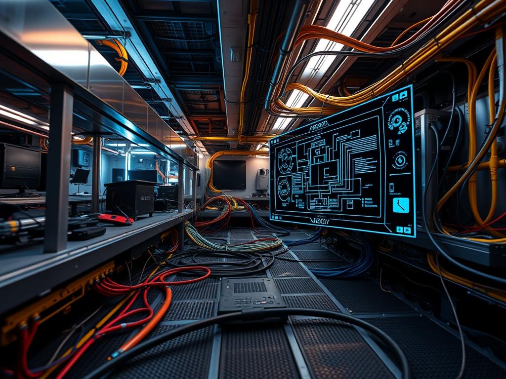
Underfloor cable management represents the fundamental physical abstraction layer in modern data center architecture and high-density computing environments. It serves as the bridge between modular power distribution and the logical network fabric; facilitating the transport of high-capacity data payloads while maintaining the structural and thermal integrity of the facility. The primary role of this infrastructure is to resolve the conflict between escalating cable density and the strict requirements for laminar airflow in raised-floor environments. Without precise organizational protocols, massive cable deployments induce air turbulence, create hotspots, and contribute to significant signal-attenuation through electromagnetic interference. This manual addresses the dual challenge of mechanical installation and electrical signal protection. By implementing a standardized underfloor strategy, architects can reduce latency caused by retransmissions and ensure that the physical layer supports the high throughput required by contemporary cloud and edge computing clusters. The following sections detail the engineering rigor required to maintain this critical subsystem.
TECHNICAL SPECIFICATIONS
| Requirement | Default Port/Operating Range | Protocol/Standard | Impact Level (1-10) | Recommended Resources |
| :— | :— | :— | :— | :— |
| Minimum Underfloor Height | 300 mm to 900 mm | TIA-942-B | 9 | High-Grade Zinc-Plated Steel |
| Signal-to-Noise Ratio (SNR) | > 25 dB for 10GbE | IEEE 802.3an | 8 | Cat6A Shielded Twisted Pair |
| Grounding Resistance | < 5 Ohms | NEC Article 250 | 10 | Solid-Copper-Busbar |
| Cable Fill Ratio | 40% (Initial) to 60% (Max) | TIA-569-E | 7 | Polymer-Cable-Trays |
| EMI Clearances | 120 mm to 300 mm | ISO/IEC 11801 | 9 | Aluminum-Conduit |
| Monitoring Interface | Port 161 (SNMP) | SNMPv3 | 6 | 2GB RAM / 1 vCPU per Node |
THE CONFIGURATION PROTOCOL
Environment Prerequisites:
1. Compliance with NFPA-75 for fire protection in information technology equipment areas.
2. Verified Structural-Floor-Loading capacity of 1,200 kg/m2 minimum.
3. Access to AutoCAD or Revit floor maps for coordinate-based asset placement.
4. Validation of the Master-Grounding-Busbar connectivity to the building’s primary earth source.
5. All installers must possess OSHA-10 or equivalent safety certifications for electrical sub-floor work.
Section A: Implementation Logic:
The engineering design of underfloor cable management is predicated on the principle of electromagnetic segregation. In its baseline state, physical data transmission is susceptible to induction: a phenomenon where power cables generate electromagnetic fields that fluctuate in accordance with the current load. This induction creates noise on adjacent copper data lines, leading to packet-loss and increased latency as higher-level protocols must manage error correction for corrupted frames.
The implementation logic requires an idempotent deployment of physical pathways; meaning that the layout must be repeatable and predictable across the entire data hall. We utilize a tiered hierarchy: the lowest level is reserved for high-voltage power distribution, while the upper level, closest to the floor tiles, is reserved for data-bearing fiber and copper. This vertical separation leverages the inverse square law of electromagnetism to minimize the impact of EMI on signal fidelity. Furthermore, all transitions from horizontal to vertical planes must respect the minimum bend radius of the media to prevent internal refraction in fiber optics or structural deformation in copper conductors.
Step-By-Step Execution
Grid Mapping and Coordinate Calibration
Identify the origin point (0,0) of the data hall and utilize a Laser-Level to project the Raised-Floor-Grid. Mark all pedestal locations using Indelible-Ink on the Slab-Floor.
System Note: This action establishes the physical lattice upon which all routing logic depends. Misalignment at this stage results in cumulative drift which compromises the integrity of the floor tiles and creates mechanical stress on the Pedestals.
Pedestal and Stringer Assembly
Install Zinc-Plated-Pedestals at every grid intersection. Fasten System-Stringers using Self-Tapping-Bolts to create a rigid, lateral support structure.
System Note: The stringer assembly provides the necessary torque resistance to prevent floor shift during heavy cable pulls. This ensures the structural overhead remains stable as the load-bearing requirements scale.
Pathway Installation and Bonding
Mount the Underfloor-Cable-Trays (preferred: wire mesh) onto the pedestal heads using C-Brackets. Connect every section of the tray to the Signal-Reference-Grid (SRG) using #6-AWG-Copper-Jumpers.
System Note: This creates a common-mode voltage reference. It ensures that the tray acts as a Faraday cage, mitigating the effects of external electromagnetic fields on the encapsulated cables.
Power Feed Distribution
Deploy Liquid-Tight-Flexible-Conduit for high-voltage power runs. These must be anchored to the Slab-Floor at intervals of 1.5 meters using Steel-Clamps.
System Note: Anchoring the conduit prevents mechanical movement during high-current surges (fault conditions) and maintains the mandatory distance from the data pathways to prevent signal-attenuation.
Data Media Population
Route Cat6A and OM4-Fiber cables into their respective trays. Use Hook-and-Loop-Fasteners (not plastic zip ties) to secure bundles at 1-meter intervals.
System Note: Securing the media prevents cable migration and thermal-inertia pockets. Avoid over-tightening to ensure the internal twist rate of the copper pairs is maintained, which is critical for Crosstalk-Cancellation.
Signal Validation and Certification
Utilize a Fluke-DSX-8000 to perform a permanent link test on every copper run. Generate a PDF-Report documenting the Return-Loss, NEXT (Near-End Crosstalk), and ACR-F (Attenuation-to-Crosstalk Ratio, Far-end).
System Note: This step verifies that the physical layer adheres to the planned SNR specifications. If the throughput fails to meet IEEE 802.3 standards, the link must be re-terminated or re-routed.
Section B: Dependency Fault-Lines:
The most common point of failure in underfloor cable management is the violation of the Bend-Radius-Limit. When a cable is bent too sharply, the internal geometry of the pairs changes, increasing the latency and causing reflected signals known as Return-Loss.
Another mechanical bottleneck occurs when cable volume exceeds 60% of the tray’s cross-sectional area. This reduces the thermal-efficiency of the environment; the cables act as a physical barrier to the cold air being pushed through the plenum. This can cause the Intake-Temperatures at the server rack to rise, triggering thermal throttling in the CPU-Kernels of the hosted hardware. Lastly, a failure to maintain Grounding-Continuity between tray sections can lead to “floating” potentials, which creates a significant risk for electrostatic discharge (ESD) during maintenance.
THE TROUBLESHOOTING MATRIX
Section C: Logs & Debugging:
While cable management is physical, its performance is visible in the logical management layer. Monitor the systemctl status snmpd service to ensure telemetry data is flowing from the environmental sensors. If a link shows high packet-loss, execute the following diagnostic workflow:
1. Check Physical Connectivity: Locate the cable in the Asset-Database using its Unique-ID.
2. Analyze SNR Logs: Access the network switch via SSH and run the command show interfaces counters errors. High counts of CRC-Errors or Frame-Check-Sequence (FCS) failures indicate EMI or a damaged cable.
3. Sensor Readout Verification: Check the Thermal-Sensors located in the sub-floor via the BMS-Console (Building Management System). If the temp exceeds 25 degrees Celsius, inspect for airflow obstructions.
4. Visual Fault Location: For fiber optic links, use a Visual-Fault-Locator (VFL); a red laser will visible through the jacket at the point of a macro-bend or break.
5. Grounding Verification: Use a Fluke-Multimeter to test the potential difference between the tray and the Main-Earthing-Terminal. Any reading above 0.5V AC requires a re-inspection of the Bonding-Jumpers.
OPTIMIZATION & HARDENING
Performance Tuning:
To maximize throughput, implement a “Side-Car” routing strategy where high-frequency data cables are placed in trays with solid bottoms to provide 100% EMI shielding from power cables below. Optimize the concurrency of cable deployments by utilizing pre-terminated trunks; this reduces the time the floor tiles are open, maintaining the air pressure within the plenum.
Security Hardening:
Physical security is as vital as the firewall. Install Underfloor-Enclosure-Locks on all access tiles. Ensure that any Out-of-Band (OOB) management cables are routed in separate, color-coded Orange-Conduit to prevent unauthorized access or accidental disconnection during routine maintenance. Apply strict chmod 600 permissions to the digital maps of the cable plant to prevent reconnaissance by internal threats.
Scaling Logic:
The setup is designed for modularity. As rack density increases, the underfloor cable management system can be expanded by adding “Bridge-Trays” between existing rows. Always maintain a 20% growth buffer in the fill-ratio. When scaling, use idempotent configuration scripts for the network switches to automatically provision new ports as they are physically connected.
THE ADMIN DESK
1. How do I fix high CRC errors?
Identify the cable path and check for proximity to 480V power lines. Ensure all Bonding-Jumpers are secure. If the cable is near a variable frequency drive (VFD), it must be moved to an Aluminum-Conduit for better shielding.
2. The floor tiles are vibrating; is this a problem?
Yes. Vibration indicates air turbulence. Check the underfloor cable management trays for high-profile blocks that are obstructing the fans. Rearrange cables to allow for a clearer airflow path to the Perforated-Tiles.
3. Can I mix Fiber and Copper in the same tray?
Technically yes, but it is not recommended. If inevitable, place the Fiber-Optics on top of the Copper-Cables to prevent the weight of the copper from crushing the glass cores; maintaining optimal latency and signal integrity.
4. What is the best way to label underfloor runs?
Use Polyester-Wrap-Around-Labels at every transition point (where a cable enters or exits the sub-floor). Labels should include the Source-Rack, Destination-Port, and VLAN-ID for rapid troubleshooting during an outage.
5. How often should I audit the sub-floor?
Perform a visual inspection and thermal scan every 6 months. Use a Thermal-Imaging-Camera to detect hotspots caused by blocked air or overloaded power circuits. Document all changes in the DCIM-Software.

