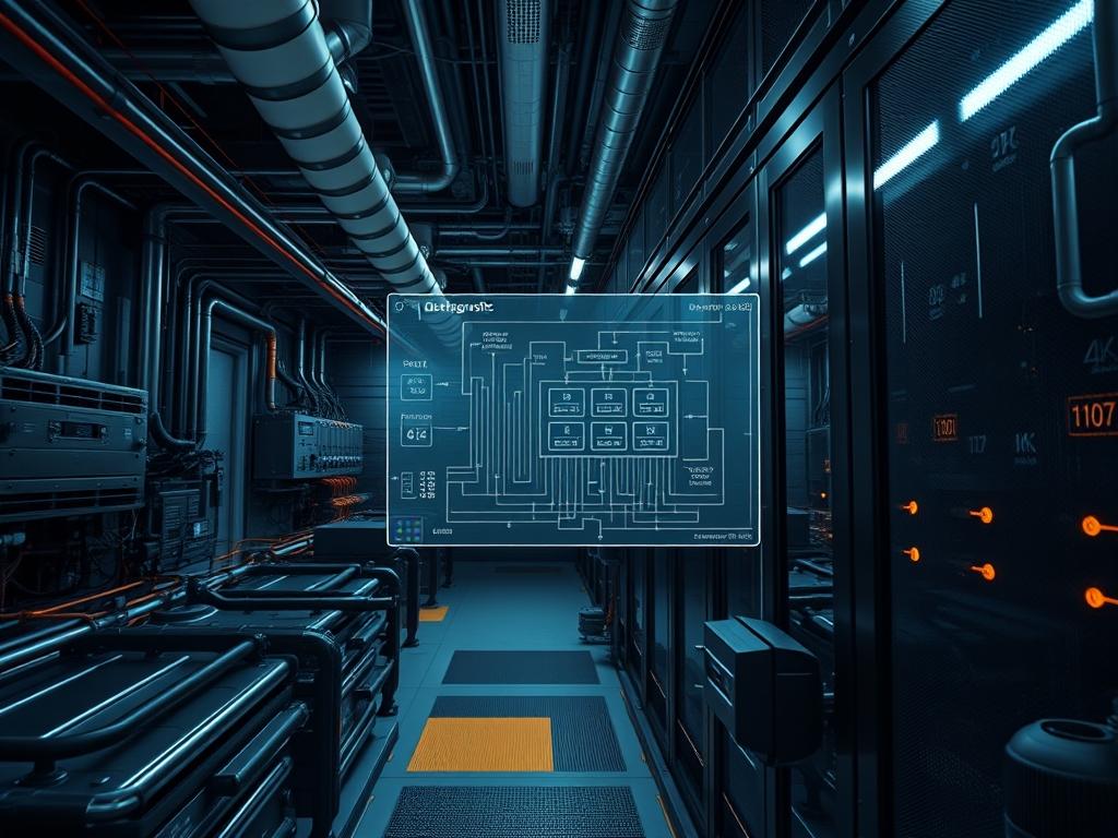
Data center fire suppression occupies a critical layer within the facility infrastructure stack; specifically bridging the gap between mechanical life safety and the steady-state continuity of digital assets. Unlike traditional aqueous systems that introduce high thermal-inertia hazards and catastrophic electrical conductivity; modern suppression utilizes gaseous agents such as Inergen, FM-200, or Novec 1230 to neutralize thermal events without damaging high-density compute nodes. This integration is not merely a physical utility; it is a programmed safeguard that must interact with the Building Management System (BMS) and Network Operations Center (NOC) logic. The primary problem involves the mitigation of combustion while preventing the acoustic shock or residue-based signal-attenuation that often accompanies chemical release. By implementing precise inert gas pressure metrics, architects ensure that the suppression payload is delivered with minimal latency, maintaining an idempotent state where the hardware remains viable post-discharge. This manual outlines the engineering design, monitoring protocols, and logic-gate configurations required for a resilient fire lifecycle.
Technical Specifications
| Requirement | Default Port/Operating Range | Protocol/Standard | Impact Level (1-10) | Recommended Resources |
| :— | :— | :— | :— | :— |
| Gaseous Agent Pressure | 360 – 600 PSI | NFPA 2001 | 10 | ASME B31.1 Piping |
| Acoustic Nozzle Peak | < 110 dB | ISO 14520 | 8 | Acoustic Dampening Kits |
| Monitoring Frequency | 1Hz – 10Hz Polling | IEEE 802.3 (PoE) | 7 | 2 vCPU / 4GB RAM |
| Actuation Delay | 30 – 60 Seconds | UL 2166 | 9 | PLC Logic Controller |
| Logic-Gate Reliability | 99.999% Uptime | MODBUS / BACnet | 10 | ECC Memory Systems |
| Air Changes / Hour | 1.0 – 2.5 ACH | ASHRAE 90.4 | 6 | HVAC Damper Actuators |
The Configuration Protocol
Environment Prerequisites:
Installation requires strict adherence to NFPA 72 (National Fire Alarm and Signaling Code) and NFPA 2001 (Standard on Clean Agent Fire Extinguishing Systems). Technical dependencies include high-sensitivity smoke detection (HSSD) like VESDA firmware version 4.2 or higher. The logic-controller must have root-level access to the Honeywell EBI or Schneider EcoStruxure automation server. Users must possess Level II NICET certification for physical assembly and administrative sudo privileges for the building management software interface.
Section A: Implementation Logic:
The engineering design utilizes the concept of chemical encapsulation: the suppression zone is treated as a sealed environment where gas concentration must reach 4.7 percent to 12 percent volume depending on the specific agent. The “Why” behind this protocol centers on the disruption of the fire tetrahedron through oxygen displacement or thermal heat absorption. This setup relies on a “Cross-Zoned” detection sequence; the system will not initiate a discharge payload until two distinct sensors confirm the fire event. This logic prevents accidental releases that would otherwise lead to massive operational overhead and potential hardware damage from acoustic vibrations.
Step-By-Step Execution
1. Calibrate Pressure Transducers and Monitor Hubs
Connect the fluke-multimeter to the Analog Input (AI) terminals of the Logic-Controller. Verify that the 4-20mA loop correctly maps to the physical pressure range of 0 to 600 PSI.
System Note: This action ensures the physical pressure analog signal is accurately digitized in the controller kernel. This prevents false positives in the monitoring service that could trigger unnecessary throughput limits on the HVAC system.
2. Configure the Suppression Service Daemon
Access the system terminal and execute systemctl enable fire-suppression.service. Navigate to /etc/fire-suppression/config.yaml and define the high-pressure and low-pressure thresholds.
System Note: Modifying this configuration file establishes the software boundaries for the logic-controllers. The service monitors the concurrency of sensor inputs to determine if a discharge state is imminent.
3. Initialize Solenoid Actuator Logic
Run the command chmod +x /usr/bin/actuage-solenoid to grant execution permissions to the actuation script. Verify the circuit continuity to the Master Cylinder Solenoid using a terminal-based diagnostic tool such as sensors-view.
System Note: This step ensures that the software-to-hardware bridge is secure. If the logic fails, the physical agent remains trapped in the cylinder, rendering the entire suppression strategy useless during a thermal event.
4. Set Dampers to Fail-Safe State
Configure the HVAC Interlock via the MODBUS protocol. Set the register 40001 to a value of 1 to trigger immediate damper closure upon fire detection.
System Note: Closing the dampers provides the necessary room integrity to maintain gas concentration. Failure here results in agent leakage, reducing the effectiveness of the suppression payload.
5. Validate Acoustic Shielding Profiles
Deploy the Acoustic-Nozzle-Shield hardware. In the monitoring software, adjust the Acoustic_Profile variable to match the specific decibel rating of the deployed nozzles.
System Note: High-velocity gas discharge creates sound pressure levels that cause mechanical vibration in Hard Disk Drives (HDDs). This step reduces the risk of data corruption by adjusting the discharge throughput to safe acoustic levels.
Section B: Dependency Fault-Lines:
Hardware bottlenecks typically manifest at the Manifold Connection Point where friction loss can reduce discharge throughput. On the software side, packet-loss in the BACnet communication string can delay the actuation signal. If the latency between the HSSD and the Logic-Controller exceeds 500ms, the system may fail to suppress a fast-moving fire before it reaches the “Flashover” stage. Ensure that the network switch prioritizing fire traffic has Quality of Service (QoS) tags set to the highest priority to avoid congestion from standard data traffic.
The Troubleshooting Matrix
Section C: Logs & Debugging:
When a fault occurs, check the system log path at /var/log/fire_suppression/audit.log.
Error Code: 0xEF4-LOW_PRESS
Physical Indicator: Pressure gauge on cylinder A1 is below 300 PSI.
Solution: Inspect the O-ring seals on the manual override pull station. If the seal is intact, use a leak detector on the Pressure Transducer threading.
Error Code: 0xTS2-COMM_TIMEOUT
Physical Indicator: Yellow LED flashing on the BMS Gateway.
Solution: Review netstat output for UDP Port 47808 (BACnet default). Check for physical signal-attenuation in the twisted-pair cabling. Use ping -s 1500 to test for fragmentation or packet-loss on the dedicated safety VLAN.
Error Code: 0xAC7-ZONE_FLT
Physical Indicator: Ambient smoke sensors show “Trouble” status on the main panel.
Solution: Inspect the VESDA air filters. High dust concentration in the rack aisles often creates a layer of debris on the sensing laser; triggering a false “Trouble” state that prevents the suppression logic from reaching a “Ready” status.
Optimization & Hardening
Performance Tuning:
To maximize efficiency, optimize the concurrency of the air sampling system. Adjust the fan speed on the HSSD units to increase the “Air Changes Per Hour” (ACH) sensing rate without creating excessive noise. Increase the polling frequency of the pressure sensors from 1Hz to 5Hz to reduce the latency of leak detection. This proactive monitoring ensures that the agent is always at a ready state with sufficient pressure to overcome the thermal-inertia of the server racks.
Security Hardening:
The suppression network must be physically and logically air-gapped from the guest or public-facing internet. Implement strict iptables rules to allow only MODBUS and SSH traffic from the management jump-box. Hardening the PLC involves disabling all unused services (e.g., Telnet, HTTP) and enforcing 256-bit encryption on the payload of every diagnostic report sent to the NOC. Use chmod 600 on all sensitive credential files stored within the /etc/fire-suppression/ directory.
Scaling Logic:
In a multi-tenant or hyperscale environment, scaling is achieved through “Modular Zone Isolation”. Each data hall should have its own bank of cylinders connected via a common header with Selector Valves. This allows the suppression system to scale as new square footage is added without requiring a full system shutdown. The software must be designed as an idempotent service; adding a new zone to the configuration file should not affect the operational status of existing zones.
THE ADMIN DESK
1. How do I stop an accidental discharge?
Locate the Abort Station near the exit. Press and hold the manual dead-man switch. This interrupts the logic-controller timer. Release only when the E-Stop has been software-verified or the threat is neutralized within the panel.
2. What causes a ‘Pressure Loss’ alert when tanks are full?
This is often due to signal-attenuation in the transducer wiring. Check for electromagnetic interference (EMI) if the sensor cables are run too close to high-voltage power grains. Ensure all shielded cables are properly grounded.
3. Can I use water mist instead of inert gas?
Water mist is viable but introduces higher overhead regarding cleanup and potential moisture-driven signal-attenuation. Gaseous agents are preferred for high-density environments where electronics must remain energized during the suppression event.
4. Why is the countdown timer not starting?
The system requires a “Cross-Zone” confirmation. If only one sensor detects smoke, the logic remains in “Pre-Alarm” state. Check the secondary sensor zone for a “Clean” reading or a hardware malfunction in the detector logic.
5. How often should I backup the suppression logic?
Perform an idempotent backup of the PLC ladder logic and the /etc/fire-suppression/ directory after every configuration change or every six months. Store the payload on an encrypted, off-site storage device.

