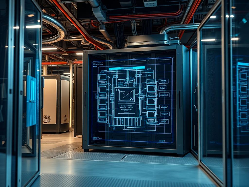
Modular infrastructure represents a paradigm shift from traditional brick and mortar facilities by decoupling the physical envelope from the underlying utility grid. A modular data center chassis serves as a pre-engineered, prefabricated housing unit that encapsulates critical compute, power, and cooling sub-systems into a single, deployable unit. This architecture addresses the inherent latency issues found in centralized hyperscale models by moving compute resources closer to the data source. The primary problem solved by this technology is the long lead time and massive capital expenditure required for traditional builds. By using a standardized chassis, organizations can achieve a rapid deployment cycle, often reducing commissioning time from years to weeks. The modular data center chassis functions as an idempotent unit of scale; deploying ten units follows the exact same logical and physical path as deploying one, ensuring predictable performance regardless of volume. This encapsulation ensures that the overhead associated with facility management is significantly reduced, allowing the technical stack to focus entirely on data throughput and payload delivery.
TECHNICAL SPECIFICATIONS
| Requirement | Default Port/Operating Range | Protocol/Standard | Impact Level (1-10) | Recommended Resources |
| :— | :— | :— | :— | :— |
| Power Density | 15kW to 45kW per Rack | IEC 60309 | 10 | Busbar / 415V 3-Phase |
| Thermal Management | 18C to 27C (Inlet) | ASHRAE Class A1-A4 | 9 | In-Row Cooling (IRC) |
| Network Backbone | 100GbE / 400GbE | IEEE 802.3ck | 8 | OM4 Fiber / QSFP-DD |
| Management Interface | Port 623 (UDP) | IPMI 2.0 / Redfish | 7 | BMC / Logic-Controller |
| Structural Load | 1,500kg per Rack Space | IBC 2021 / Seismic | 6 | Reinforced Steel Frame |
| Fire Suppression | < 30s Discharge Time | NFPA 2001 (Clean Agent) | 8 | VESDA / Novec 1230 |
| Moisture Control | 40% to 55% RH | ISO 14644-1 | 5 | Humidification Manifold |
THE CONFIGURATION PROTOCOL
Environment Prerequisites:
Before initiating the physical assembly or logical provisioning, the site must conform to specific baseline standards. The primary electrical requirement is a grounded 3-Phase 480V input capable of handling the maximum rated payload plus a 20% margin for peak concurrency events. Network infrastructure must support IPv6 and VLAN tagging for management isolation. The site foundation must be a level concrete pad with a minimum thickness of 8 inches, rated for the static weight of the modular data center chassis. All administrative users must have root level access to the site Logic-Controller and an active SSH key pair for secure terminal interactions.
Section A: Implementation Logic:
The engineering design of the chassis mimics a closed-loop ecosystem. The goal is to maximize thermal-inertia within the cold aisle while minimizing the mixing of air streams. By utilizing hot-aisle containment, the system creates a pressure differential that forces cold air through the server blades at a constant velocity. Logically, the deployment relies on a Modular BMC (Baseboard Management Controller) that abstracts the hardware layer. This allows the administrator to push configuration profiles via a CI/CD pipeline directly to the chassis, ensuring that every component from the PDU (Power Distribution Unit) to the CRAC (Computer Room Air Conditioner) behaves as a single programmable entity.
Step-By-Step Execution
1. Structural Anchoring and Leveling
Position the chassis over the designated utility entry points. Use a laser-level and industrial-jacks to ensure the frame is perfectly horizontal. Secure the unit using M20 expansion bolts at all four corners of the base frame.
System Note: Proper leveling prevents mechanical stress on the backplane connectors and ensures that the liquid cooling loops do not develop air pockets due to gravity-induced fluid imbalances.
2. Power Integration and Busbar Verification
Connect the primary feeders to the Automatic Transfer Switch (ATS). Verify phase rotation using a fluke-multimeter prior to energizing the internal Busbar. Execute the command sensors –check-power (or equivalent on the local controller) to verify current draw.
System Note: This step validates the electrical path from the utility source to the rack-level PDUs, ensuring that high concurrency during server boot-up does not trigger a false-positive overcurrent trip.
3. Cooling Loop Pressurization
Fill the secondary cooling loop with inhibited glycol or treated water. Use the logic-controller to activate the pumps at 25% capacity. Check for leaks at every quick-disconnect fitting. Gradually increase pressure until the flow rate reaches the design specification (e.g., 50 GPM).
System Note: Pressurization stabilizes the thermal-inertia of the chassis; any drop in pressure will trigger an immediate interrupt signal to the CPU throttles to prevent thermal runaway.
4. Logic-Controller and IPMI Provisioning
Connect a terminal to the OOB (Out-of-Band) management switch. Assign a static IP to the Logic-Controller by editing /etc/network/interfaces or using the nmcli tool. Run systemctl start chassis-manager to initiate the monitoring daemon.
System Note: The management daemon facilitates the encapsulation of hardware telemetry into a single stream, allowing for remote monitoring of fan speeds, voltages, and intake temperatures.
5. Network Convergence and Fiber Certification
Inspect all fiber optic jumpers for signal-attenuation using an OTDR (Optical Time-Domain Reflectometer). Plug the uplinks into the Leaf Switches and verify link aggregation. Run ping -s 1500 -c 100 [gateway_ip] to check for packet-loss.
System Note: High-speed data links are sensitive to dust and micro-bends; certifying the fiber path ensures maximum throughput for the internal backbone while keeping latency within the sub-millisecond range.
Section B: Dependency Fault-Lines:
Failures often occur at the intersection of disparate systems. A common mechanical bottleneck is the Ventilation Damper assembly; if the actuators fail to open during a cooling cycle, the interior temperature will spike within seconds. On the logical side, library conflicts within the Python-based Logic-Controller can prevent the Modbus sensors from reporting data to the dashboard. Always ensure that the libmodbus and pyserial libraries are locked to specific versions in the deployment manifest to maintain an idempotent state. Another common fault is signal-attenuation caused by improper bend radii in the overhead cable trays, which directly impacts the net throughput of the network fabric.
THE TROUBLESHOOTING MATRIX
Section C: Logs & Debugging:
When a fault occurs, the primary diagnostic source is the chassis-event-log located at /var/log/chassis/events.log. Physical fault codes are also displayed on the exterior LED Status Panel.
1. Error Code E-104 (Thermal Excursion): This indicates that the intake temperature has exceeded the ASHRAE limit. Check the /sys/class/thermal/ path for individual sensor readouts. Verify that the IRC fans are not in a stalled state.
2. Error Code E-209 (PDU Communication Failure): This usually stems from a packet-loss issue on the internal management VLAN. Use tcpdump -i eth1 port 161 to verify if SNMP polls are reaching the PDUs.
3. High Latency / Low Throughput: Inspect the switch logs via show interfaces counters errors. If CRC errors are incrementing, replace the SFP+ modules or clean the fiber end-faces.
4. Logic-Controller Hang: If the API becomes unresponsive, check for a deadlock in the concurrency handler by running htop to identify runaway processes. Restart the service using systemctl restart chassis-manager.
OPTIMIZATION & HARDENING
Performance Tuning:
To achieve maximum efficiency, the cooling subsystem should be tuned for the specific payload profile. If the servers demonstrate high thermal-inertia, you can lower the fan curve to save power without risking an overheat event. Use the ethtool -G command to increase ring buffer sizes on the network interfaces, which helps manage high throughput spikes without dropping packets.
Security Hardening:
Disable all unnecessary services on the Logic-Controller. Use iptables or nftables to restrict access to the management ports (623, 443, 22) to a specific Admin Subnet. Ensure that the PDU and UPS units are on a physically isolated network to prevent Man-in-the-Middle (MitM) attacks on the power infrastructure. Implement fail-safe physical logic where a total loss of control signal defaults the cooling fans to 100% speed.
Scaling Logic:
When expanding the cluster, use a Spine-Leaf architecture to maintain consistent latency across multiple chassis. The internal DHCP server for the IPMI network should be configured with a sufficiently large pool to accommodate future nodes. As you add more units, the total thermal-overhead must be recalculated to ensure the site-wide Chilled Water Loop or DX units can handle the cumulative heat rejection.
THE ADMIN DESK
How do I reset the Logic-Controller to factory defaults?
Access the terminal via the Serial Console and execute chassis-factory-reset –force. This will wipe all VLAN configurations, custom fan curves, and local users. The system will reboot into a discovery mode for re-provisioning.
What causes the “Phase Imbalance” warning on the PDU?
This occurs when the payload is not distributed evenly across the L1, L2, and L3 legs of the power feed. Re-rack servers to balance the amperage, ensuring the delta between phases is less than 10 percent.
Why is the network throughput capped at 10Gbps on a 100Gbps link?
Check for a MTU (Maximum Transmission Unit) mismatch. Ensure that Jumbo Frames (9000 bytes) are enabled across the entire path, from the virtualized NIC to the core switch, to reduce packet overhead.
How do I update the chassis firmware without downtime?
The Logic-Controller supports an A/B Partition update strategy. Upload the new image to the inactive partition using fw-update –stage [path_to_image]. The system will switch to the new version upon a warm reboot of the controller only.
What is the fastest way to detect a leak in the cooling loop?
Monitor the Pressure-Differential sensor at the CDU (Cooling Distribution Unit). Any sustained drop in PSI while the pumps are at a constant RPM indicates a breach. The Logic-Controller will log this as a Critical Leak event.

