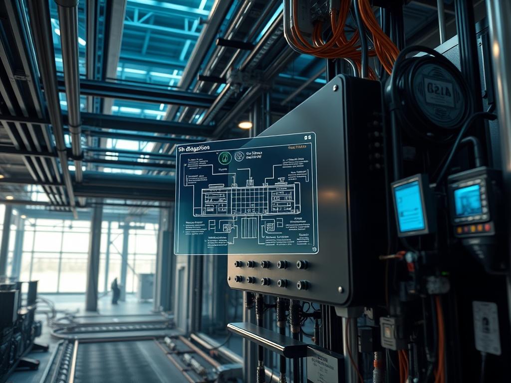
High voltage dc distribution represents a fundamental shift in how modern mission critical facilities manage energy conversion and transport. Traditional three phase AC architectures introduce significant overhead through multiple transformation stages; including rectification and inversion; that degrade overall system efficiency. By adopting high voltage dc distribution, specifically at the 380V to 400V DC nominal level, infrastructure architects reduce the number of power conversion steps from five to two. This reduction minimizes the cumulative latency of voltage regulation and mitigates the skin effect associated with alternating current, which allows for more efficient use of copper in the distribution busway. In a standard cloud scale facility, this transition eliminates harmonic distortion issues and the need for phase balancing, resulting in a 7% to 15% improvement in end to end energy throughput. This manual details the engineering requirements for deploying, managing, and optimizing a 380V high voltage dc distribution fabric within a software defined power environment.
TECHNICAL SPECIFICATIONS
| Requirement | Default Port/Operating Range | Protocol/Standard | Impact Level (1-10) | Recommended Resources |
| :— | :— | :— | :— | :— |
| Nominal Voltage | 380V DC (+/- 10V) | ETSI EN 300 132-3-1 | 10 | 99.99% Electrolytic Copper |
| Control Interface | Port 502 (Modbus/TCP) | IEC 61850 | 7 | Quad-Core ARM / 4GB RAM |
| Circuit Protection | 1.25x Rated Current | IEC 60947-2 | 9 | Solid-State Breaker (SSCB) |
| Isolation Resistance | > 500 M-Ohm | IEEE 802.3bt | 8 | XLPE Insulation Grade |
| Thermal Threshold | 65C (Operating) | SNMPv3 / IPMI | 6 | Liquid Cooling Loop |
THE CONFIGURATION PROTOCOL
Environment Prerequisites:
Successful deployment requires strict adherence to NFPA 70 (National Electrical Code) Article 706 for energy storage systems and IEC 60364-7-712 for solar and battery integration. The management layer must be hosted on a Linux based controller running Kernel 5.15+ to support real time hardware interrupts and efficient I/O handling for sensor arrays. All administrative users must have sudo privileges and be members of the dialout and power groups to interact with serial controllers and power distribution units. Verify that all fluke-multimeters used for calibration have a CAT IV rating to handle high energy transients during initial busbar energization.
Section A: Implementation Logic:
The transition to high voltage dc distribution is driven by the logic of payload optimization. In AC systems, the payload (energy) is subject to reactive power losses and a non unity power factor. DC distribution removes the phase angle dependency, ensuring that the voltage and current are always in phase. This creates an idempotent power state where the energy delivered is strictly a function of voltage and resistance, simplifying the control algorithms. Furthermore, the thermal-inertia of a DC system is more predictable than AC, as the lack of frequency oscillations reduces the eddy current losses in metallic enclosures. This allows for higher density rack configurations without exceeding the thermal limits of the facility air handling units.
Step-By-Step Execution
1. Initialize Primary Rectifier Modules
Access the power control module via ssh admin@power-controller.local and execute the command systemctl start hv-rectifier.service.
System Note: This command initiates the boot sequence for the primary AC-to-DC rectification bridge. The service checks the status of the insulated-gate bipolar transistors (IGBTs) to ensure no shorts are present before closing the primary contactor.
2. Configure DC Busbar Isolation Monitoring
Navigate to the configuration file at /etc/power/isolation.conf and set the variable MIN_ISOLATION_OHMS=500000.
System Note: High voltage dc distribution requires constant monitoring of the leakage current to ground. By setting this threshold, the system will trigger an automatic disconnect if a dielectric breakdown occurs, protecting the downstream IT load from potential chassis energization.
3. Calibrate Voltage Throughput via Logic Controller
Use the modbus-cli tool to write a value of 3800 to register 40001 by running modbus-write –address 192.168.10.50 –register 40001 –value 3800.
System Note: This sets the target output voltage of the central distribution unit. The logic controller uses this value as the setpoint for its Proportional-Integral-Derivative (PID) loop to maintain stability under varying load conditions, minimizing latency in voltage response during transient events.
4. Deploy Solid-State Circuit Breaker (SSCB) Policies
Load the breaker logic firmware using firmware-load –target sscb-cluster-01 –file /bin/hv-breaker-v2.bin.
System Note: Unlike mechanical breakers, SSCBs offer sub-millisecond interruption speeds. Loading this firmware ensures the concurrency of fault detection across all branch circuits, preventing a localized short from propagating back to the primary transformer.
5. Verify Signal-Attenuation in Monitoring Loops
Run the diagnostic script check-signal-integrity –interface rs485-01 –baud 115200.
System Note: High voltage environments generate significant electromagnetic interference (EMI). This script checks for packet-loss in the Modbus communication stream between the busbar sensors and the management console, ensuring that the reported telemetry matches the physical reality of the bus.
Section B: Dependency Fault-Lines:
Electronic components within the distribution chain are highly sensitive to ripple voltage. A common failure point is the degradation of dc-link capacitors within the Point-of-Load (POL) converters. If the throughput of the filtering stage drops, the ripple can introduce noise into the server power supplies, leading to mysterious reboots or data corruption within the NVMe storage layer. Additionally, library conflicts in the power management software; specifically between libmodbus and newer python3-pymodbus wrappers; can cause race conditions during high concurrency polling intervals. Architects must ensure that all telemetry scripts are idempotent to prevent double-counting of energy usage metrics during a service restart.
THE TROUBLESHOOTING MATRIX
Section C: Logs & Debugging:
Physical faults in the high voltage dc distribution fabric are often preceded by specific error strings in the system journal. Use the command journalctl -u hv-distro-daemon.service -f to monitor real time logs.
Error String: ERR_GROUND_FAULT_DETECTED [0x08]
Instruction: This indicates that the insulation resistance has dropped below the threshold defined in /etc/power/isolation.conf. Immediately inspect the cable jackets at the entry points to the rack for signs of mechanical abrasion or thermal-inertia related deformation.
Error String: WARN_VOLTAGE_SAG_TRANSIENT [0x12]
Instruction: This warning highlights a dip in the DC bus voltage below 360V. Check the upstream rectifier redundancy status using hv-rectifier-cli –status. This is often caused by a failed rectifier module or an unexpected surge in the IT payload that exceeds the current limiters.
Visual Cue Analysis: If the LED indicator on the fluke-376-fc shows a red strobe pattern during a busbar test, it signifies a phase mismatch in the AC input before rectification. If the liquid cooling manifold shows a purple hue in the coolant return line, check for electrolytic corrosion within the cold plates of the high density power modules.
OPTIMIZATION & HARDENING
Performance Tuning:
To maximize throughput, adjust the switching frequency of the DC-DC converters. Higher frequencies reduce the physical footprint of the magnetic components but increase switching losses. A frequency of 100kHz is recommended for balancing efficiency and thermal-inertia management. Use the command power-tune –frequency 100000 to apply these settings across the cluster.
Security Hardening:
The high voltage dc distribution control plane must be isolated from the public network. Limit access to the IPMI and SNMP interfaces using iptables or nftables at the hardware gateway.
Example firewall rule: nft add rule ip filter INPUT ip saddr 10.0.0.0/24 tcp dport 502 accept.
This ensures that only the management subnet can send control commands to the power fabric, preventing unauthorized voltage manipulation which could lead to physical asset destruction.
Scaling Logic:
Maintain a modular approach by utilizing N+1 or 2N redundancy models. When scaling the distribution fabric, ensure that the encapsulation of the busbar remains continuous to prevent signal-attenuation in the localized grounding sensors. As the load increases, monitor the overhead of the distribution system; if conversion losses exceed 2%, investigate the health of the primary rectifier diodes.
THE ADMIN DESK
1. How do I reset a tripped SSCB?
Execute sscb-ctrl –reset –id breaker-04. If the fault persists, the command will fail and return a status code of 0x05, indicating a permanent short circuit that requires physical inspection before further reset attempts.
2. What is the impact of cable length on DC distribution?
Longer runs increase signal-attenuation and voltage drop. Ensure that the cross-sectional area of the copper tracks is sized to keep the voltage drop under 1% at maximum throughput to maintain efficiency targets.
3. Why use 380V instead of 48V DC?
380V DC significantly reduces the current required for the same power payload. This allows for smaller cable diameters; reducing copper costs and weight; while also minimizing IR losses across the distribution network.
4. Can I hot-swap rectifier modules?
Yes; assuming the system is configured for concurrency. Use the command rectifier-ctrl prepare-swap –id mod-02 to safely divert the load to redundant modules before physically removing the hardware from the chassis.
5. How is grounding managed in a 380V DC environment?
A high-resistance midpoint ground is typically employed. This configuration limits the fault current during a ground event, allowing the system to continue operating while the administrator identifies the source of the isolation breakdown.

