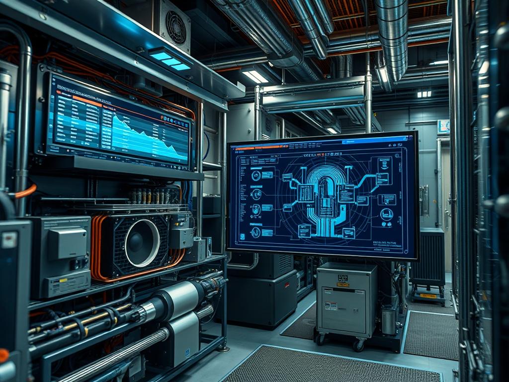
Cooling failure response times represent the critical temporal delta between the cessation of mechanical heat rejection and the execution of a protective thermal shutdown. In high-density computing environments, the rapid accumulation of heat creates a situation where thermal-inertia dictates the survival of the hardware. If the monitoring stack fails to trigger an idempotent response within a defined window, the resulting thermal-runaway can lead to permanent silicon degradation or total system failure. This manual outlines the architecture required to manage these response times within the broader technical stack, focusing on the intersection of facility-level cooling (HVAC/CRAC) and rack-level thermal management. The objective is to minimize latency in the signal chain, ensuring that the payload of a shutdown command reaches the kernel before T-junction temperatures are breached. Accurate measurement of cooling failure response times is the primary defense against catastrophic infrastructure loss during power fluctuations or mechanical pump failures.
Technical Specifications
| Requirement | Default Range | Protocol/Standard | Impact Level | Recommended Resources |
| :— | :— | :— | :— | :— |
| Sensor Polling Rate | 500ms to 2000ms | IPMI 2.0 / SNMPv3 | 10 | 256MB RAM / Low Latency |
| Thermal Threshold (Warning) | 75C to 80C | ACPI / IEEE 1149.1 | 6 | Standard CPU Cycles |
| Thermal Threshold (Critical) | 85C to 95C | PECI 3.0 | 9 | High Priority Interrupt |
| Shutdown Execution Time | < 5 Seconds | Modbus/TCP / SSH | 10 | Non-blocking I/O |
| Coolant Flow Velocity | 1.5 to 3.0 m/s | Analog 4-20mA | 8 | Flow Meter / PLC |
| Ambient Rack Airflow | 500 to 1200 CFM | BACnet / IP | 7 | Logic Controller |
The Configuration Protocol
Environment Prerequisites:
The deployment environment must adhere to NFPA 70 (NEC) for electrical safety and ASHRAE TC 9.9 for data center thermal guidelines. Version requirements include IPMITOOL 1.8.18 or later; Linux Kernel 5.10+ for advanced thermal_zone support; and Net-SNMP 5.9 for telemetry encapsulation. Necessary user permissions include root access for hardware-level interrupts and administrator privileges on the Building Management System (BMS) logic controllers.
Section A: Implementation Logic:
The engineering design relies on a tiered response architecture. Logic-controllers at the row level monitor flow rates and delta-T (temperature difference) values across heat exchangers. When a pump failure or compressor stall occurs, the signal-attenuation must be kept to a minimum as the data transitions from the physical sensor to the software stack. The system utilizes an idempotent logic gate: if the cooling state is “FAIL,” the shutdown command is issued repeatedly until the hardware registers a power-state change. This prevents a single packet-loss event from cascading into a hardware meltdown. The “Why” behind this design is the mitigation of thermal-inertia; even after fans stop, the heat-sink continues to dump energy into the processor, necessitating a shutdown well before the absolute maximum temperature is reached to account for this residual heat.
Step-By-Step Execution
1. Initialize Hardware Telemetry via lm-sensors
Execute the command sensors-detect to identify the on-board SMBus controllers and thermal diodes. Once identified, load the modules using modprobe i2c-dev and modprobe coretemp.
System Note: This action initializes the kernel-level drivers required to bridge the gap between the physical thermal diode and the operating system; without these modules, the thermal-inertia data cannot be ingested by the monitoring daemon.
2. Configure IPMI Thresholds for Automated Response
Utilize ipmitool -I lanplus -H [BMC_IP] -U [USER] -P [PASS] sensor thresh “CPU Temp” upper 85 90 95. This sets the non-critical, critical, and non-recoverable limits.
System Note: This command writes directly to the Baseboard Management Controller (BMC) non-volatile storage; it ensures the hardware can trigger a protective state change independently of the main operating system’s availability.
3. Establish Modbus Communication with CRAC Units
Configure the logic-controller to poll the Cooling Unit via Modbus/TCP on port 502. Map the Holding Register 40001 to the compressor status and 40005 to the fan tachometer.
System Note: By monitoring the cooling source directly, the system can anticipate a rise in temperature before the heat reaches the rack, significantly reducing cooling failure response times.
4. Deploy Emergency Power Off (EPO) Logic Scripts
Create a script at /usr/local/bin/thermal_shutdown.sh that triggers systemctl poweroff. Ensure the file is executable via chmod +x. Link this script to a udev rule or a systemd-journald trigger.
System Note: This script provides a managed teardown of services to prevent data corruption; it prioritizes throughput of the shutdown sequence over service availability.
5. Validate Signal Integrity with Fluke-Multimeter
Physically probe the Dry Contact relays on the PDU or UPS using a fluke-multimeter in continuity mode while simulating a cooling alarm.
System Note: This manual verification ensures that no physical signal-attenuation or wiring faults exist in the emergency signal path; it confirms the electrical path for the “Kill Signal” is viable.
Section B: Dependency Fault-Lines:
Software-based cooling failure response times are often hampered by latency in the SNMP polling cycle. If the throughput of the management network is saturated, critical thermal packets may experience packet-loss, delaying the shutdown. Mechanical bottlenecks include the “Latent Heat of Vaporization” in liquid-cooled systems; if the secondary loop fails, the coolant itself acts as a heat-sink for a limited time, but once it reaches a steady state, the temperature spike is nearly instantaneous. Another common failure is a conflicting BIOS/UEFI setting that overrides the OS-level thermal commands; always ensure “ACPI Critical Shutdown” is enabled in the firmware.
THE TROUBLESHOOTING MATRIX
Section C: Logs & Debugging:
When analyzing failure events, the first point of inspection is /var/log/syslog or /var/log/messages. Look for the string “Critical temperature reached” or “Machine Check Exception (MCE)”. If the system failed to shut down, verify the IPMI event log using ipmitool sel list.
For physical hardware faults, consult the logic-controller status codes. A code of E04 typically indicates an airflow obstruction, while F01 points to a pump cavitation issue. If sensor readouts appear erratic, check the cabling for EMI or signal-attenuation; ensure that high-voltage lines are not bundled with low-voltage sensor wires. Visual cues such as a flashing amber LED on the PDU usually signify a “Threshold Exceeded” state. Verify the sensor path at /sys/class/thermal/thermal_zone0/temp to ensure the kernel is receiving decimal-scaled integers consistent with physical reality.
OPTIMIZATION & HARDENING
Performance Tuning:
To improve thermal efficiency, implement a “Look-Ahead” algorithm in the logic-controller. By calculating the rate of temperature change (dT/dt), the system can trigger a shutdown when it predicts a breach, rather than waiting for the breach itself. This reduces the effective cooling failure response times by several seconds. Maximize throughput of the management network by placing thermal telemetry on a dedicated VLAN with Quality of Service (QoS) tags.
Security Hardening:
Thermal management interfaces are often vulnerable. Secure the IPMI interface by disabling Cipher 0 and enforcing strong passwords. Use firewall-cmd to restrict UDP port 161 (SNMP) and TCP port 502 (Modbus) access to known management IPs only. Ensure that the fail-safe physical logic is “Normally Closed” (NC); this way, if a control wire is cut, the system defaults to a “Fail” state and triggers the cooling response.
Scaling Logic:
In large-scale deployments, use a centralized Telegraf or Prometheus instance to aggregate thermal data. Use concurrency in the shutdown orchestration tool (such as Ansible or SaltStack) to ensure that a hundred servers can be powered down simultaneously without overwhelming the PDU switching capacity or the management network.
THE ADMIN DESK
How can I verify the actual cooling failure response time?
Perform a “dry run” by lowering the critical threshold in IPMI to a value just above current ambient. Use a stopwatch to measure the delta from the threshold breach to the final ACK of the shutdown sequence.
What is the impact of thermal-inertia on wood-frame vs. slab data centers?
Slab-based centers have higher thermal mass; they absorb heat longer. Wood-frame or modular containers have low thermal-inertia, meaning cooling failure response times must be significantly faster to prevent structural heat soak and hardware damage.
Why does my server reboot instead of shutting down during a thermal event?
This is typically caused by the “Restore on AC Power Loss” setting in the BIOS. If the thermal event causes a momentary PDU trip, the server sees the power return and attempts to restart into a high-heat environment.
Can I use software-defined fans to mitigate response time issues?
Yes; by increasing PWM fan speeds to 100% at the “Warning” threshold (e.g., 75C), you increase the thermal buffer. This provides the system more time to execute an ordered shutdown if the primary CRAC fails.

