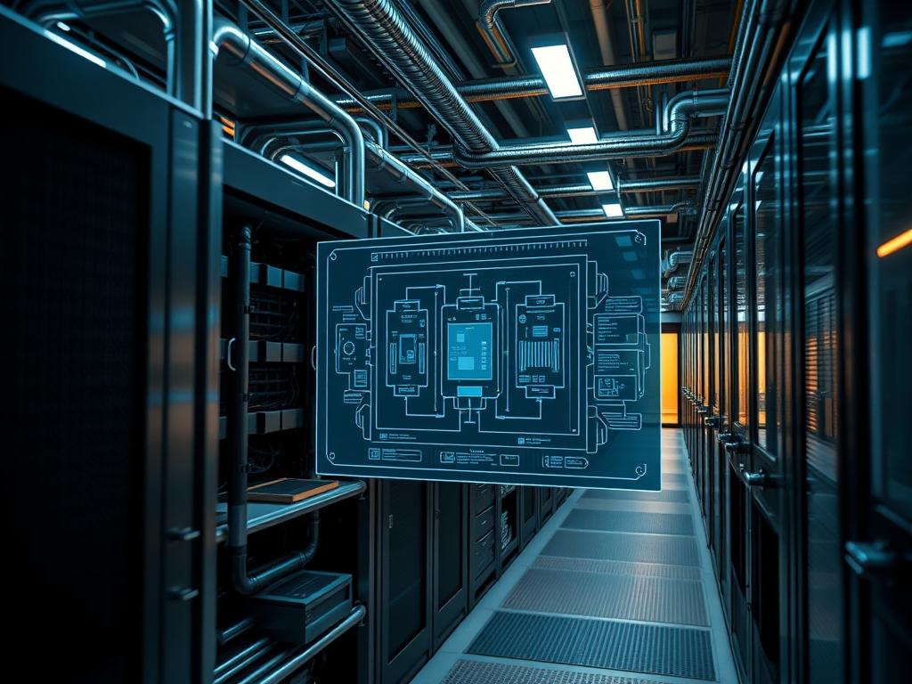
AI data center cooling is the foundational layer upon which modern high-density compute clusters reside. As AI workloads evolve from simple inference to massive distributed training involving trillions of parameters; the thermal output per rack has shifted from the traditional 10kW to 15kW range to 100kW or more. This necessitates a shift from legacy air-cooled methodologies to advanced liquid-based heat rejection systems. Within the broader technical stack: cooling infrastructure exists as a bridge between the physical facilities layer and the logical compute layer. It manages the thermal-inertia generated by high-TDP accelerators; such as the NVIDIA H100, AMD MI300X, or Nvidia Blackwell B200. Effective cooling ensures that these processors maintain peak frequency without triggering thermal throttling; which would otherwise result in significant packet-loss or increased latency across the high-speed InfiniBand or RoCE v2 fabric. This manual provides the architectural blueprint for deploying and maintaining high-density liquid cooling loops to sustain maximum computational throughput.
Technical Specifications
| Requirement | Default Port/Operating Range | Protocol/Standard | Impact Level (1-10) | Recommended Resources |
| :— | :— | :— | :— | :— |
| Secondary Loop Flow | 15 – 65 GPM per Rack | ASHRAE W3/W4 | 10 | SS316 Piping / EPDM |
| Coolant Conductivity | < 20 uS/cm | ASTM D1125 | 9 | Deionized Water (DIW) |
| Facility Inlet Temp | 18C - 32C | ASHRAE TC 9.9 | 8 | Plate Heat Exchanger |
| Monitoring Link | Port 502 / Port 161 | Modbus/TCP / SNMPv3 | 7 | PLC / Logic Controller |
| Thermal Design Power | 700W - 1200W per GPU | IEEE 1101.10 | 10 | Direct-to-Chip Cold Plates |
| Pressure Differential | 10 - 25 PSI (Delta P) | ANSI/HI 14.3 | 8 | Redundant VFD Pumps |
The Configuration Protocol
Environment Prerequisites:
Successful deployment of AI data center cooling requires strict adherence to physical and logical dependencies. Hardware must comply with NEC Article 645 for Information Technology Equipment and NFPA 75 for fire protection. Facility managers must ensure that the primary facility water system (FWS) can support the heat rejection load via a dedicated Cooling Distribution Unit (CDU). On the software layer: the Building Management System (BMS) must be configured with SNMP v3 or Modbus/TCP credentials and have read/write permissions for GPM (Gallons Per Minute) setpoints. All technicians must utilize fluke-multimeters for electrical continuity testing and pressure-transducers for loop integrity verification.
Section A: Implementation Logic:
The engineering design of AI data center cooling relies on the principle of heat transfer coefficients. Liquid cooling is vastly more efficient than air because the volumetric heat capacity of water is approximately 4,000 times that of air. By utilizing Direct-to-Chip (DTC) cooling: we eliminate the thermal resistance of the air gap between the chip and the heat sink. Instead: a cold plate is mounted directly to the Integrated Heat Spreader (IHS) of the GPU. The coolant absorbs heat directly and carries it to a heat exchanger. This design minimizes the temperature gradient (Delta T) between the junction and the coolant; allowing the chip to operate at higher clock speeds for longer durations. The logic follows a closed-loop encapsulation: where the heat is moved from the electronics to the secondary loop; then to the primary loop; and finally rejected to the atmosphere via cooling towers or dry coolers.
Step-By-Step Execution
1. Initialize the Coolant Distribution Unit (CDU)
The first step involves booting the logic controller responsible for the flow dynamics between the primary and secondary loops. Perform a system check on the local controller or via SSH using systemctl status cooling-controller.service.
System Note: This action initializes the OS-level drivers for the variable frequency drives (VFDs) and ensures the control kernel is ready to manage pump speeds based on incoming sensor data.
2. Configure Secondary Loop Pressure Setpoints
Navigate to the configuration file at /etc/thermal/thresholds.conf and define the maximum and minimum pressure limits. Use the command sed -i “s/MAX_PSI/25/g” /etc/thermal/thresholds.conf.
System Note: Setting these limits protects the Quick Disconnects (QDs) and the thin-walled cooling channels inside the Cold Plates from over-pressurization; which could lead to physical stress or rupture of the EPDM seals.
3. Calibrate Thermal and Flow Sensors
Connect the sensors to the rack-level manifold and verify the analog-to-digital (ADC) conversion. Use the tool sensors-detect to identify the I2C bus addresses for the thermistors.
System Note: Micro-calibration of flow metrics ensures that the BMS receives accurate data regarding the heat flux; allowing the system to adjust the GPM in real-time as CPU/GPU utilization spikes during training epochs.
4. Execute Leak Detection Protocol
Enable the leak detection logic-gate by running chmod +x /usr/bin/leak-monitor && ./leak-monitor –mode=active.
System Note: This service monitors the conductivity of the rope sensors placed at the base of the rack. If the conductivity increases (indicating moisture); the script triggers an immediate EPO (Emergency Power Off) and closes the solenoid valves to isolate the rack.
5. Establish Modbus Communication for Remote Telemetry
Configure the communication bridge between the rack and the facilities team using modbus-set-address –dev=/dev/ttyS0 –addr=10. Verify the payload transmission with a packet capture tool.
System Note: This ensures that the global orchestration layer can monitor the thermal efficiency and PUE across thousands of nodes; facilitating centralized control over the cooling plant.
Section B: Dependency Fault-Lines:
The most common mechanical bottleneck in AI data center cooling is the build-up of biological film or scaling within the secondary loop. If the coolant chemistry is not maintained according to ASTM D1384 standards; the thermal resistance of the cold plates will increase; leading to rapid throttling. On the logical side: library conflicts between libmodbus and the BMS firmware can lead to signal-attenuation or incorrect reporting of thermal metrics. Ensure all shared libraries are pinned to versions compatible with the hardware vendor specifications to avoid race conditions in the pump control logic.
THE TROUBLESHOOTING MATRIX
Section C: Logs & Debugging:
When a cooling failure occurs: the primary diagnostic tool is the system log located at /var/log/thermal/cdu-main.log. Search for specific error strings such as “CAVITATION_DETECTED” or “LOW_FLOW_ALARM”.
– Error E04 (Low Flow): Check for air pockets in the manifold. Use the manual bleed valve to purge air until the sound of cavitation ceases.
– Error C09 (High Conductivity): This indicates coolant contamination. Test the fluid with a fluke-multimeter in conductivity mode; if reading exceeds 20 uS/cm; the deionization (DI) canisters must be replaced.
– Error T12 (Delta T Over-limit): If the temperature difference between the inlet and outlet exceeds 15C while pumps are at 100 percent: inspect the secondary heat exchanger for fouling.
Technicians should also monitor the IPMI logs on the compute nodes to correlate high junction temperatures with PSU (Power Supply Unit) fan speeds. High fan speeds in an aqueous environment suggest that the liquid loop is failing to adsorb the total heat load; likely due to a restricted flow path.
OPTIMIZATION & HARDENING
– Performance Tuning: Adjust the PID (Proportional-Integral-Derivative) loops within the controller to reduce oscillation. A well-tuned system should reach a steady-state temperature within 180 seconds of a workload spike. Increase the “I” (Integral) gain if the system takes too long to reach the setpoint; but monitor for overshoot.
– Security Hardening: Isolate the cooling management network from the public internet using a dedicated VLAN. Implement firewall-cmd –add-service=snmp –permanent to restrict traffic only to the authorized monitoring IP. Change all default Modbus device IDs and disable unencrypted protocols like Telnet.
– Scaling Logic: When expanding the cluster: use a “Leap-Frog” cooling topology. This involves pre-plumbing the manifolds for the next ten racks and installing blanking panels on the supply lines. Ensure the CDU has enough “Head” (Vertical pressure capability) to handle the increased friction loss of the longer pipe runs.
THE ADMIN DESK
1. What is the ideal coolant for AI racks?
Use a mixture of deionized water and 25 percent propylene glycol (PG25) with proprietary corrosion inhibitors. This prevents biological growth and protects the copper-to-aluminum interfaces within the cooling loop while maintaining high heat transfer efficiency.
2. How often should filter strainers be cleaned?
Inspect strainers every 90 days during the first year of operation. AI data center cooling systems often accumulate “construction debris” in the initial months. Once the loop stabilizes: bi-annual inspections are sufficient to ensure consistent throughput.
3. Why is my PUE higher than advertised?
High PUE (above 1.2) usually indicates inefficient heat rejection at the facility level. Check if the primary pump speeds are tied to the actual load. Over-cooling at low utilization periods wastes energy and increases operational overhead significantly.
4. Can I use tap water in the secondary loop?
Absolutely not. Tap water contains minerals that cause scaling and chloride ions that induce pitting corrosion in cold plates. Always use water purified via reverse osmosis or deionization to maintain a conductivity level below 20 uS/cm.
5. How do I handle a “Thermal Runaway” alert?
Immediately drop the power ceiling for the affected nodes via ipmitool. If the temperature does not stabilize within 30 seconds: initiate a graceful shutdown of the application. Check the CDU for pump failure or a closed isolation valve.

