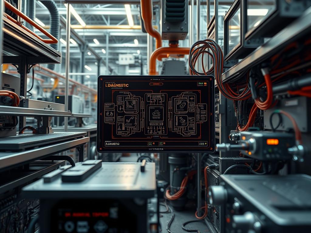
Industrial hardware mtbf (Mean Time Between Failures) serves as the primary statistical metric for assessing the reliability of critical infrastructure components. Within the contexts of energy distribution; water treatment; and high-density cloud facilities; MTBF is not merely a manufacturer specification but a live variable influenced by thermal cycles; mechanical vibration; and electrical transients. The core problem for systems architects lies in the discrepancy between theoretical MTBF ratings and actual field performance when hardware is deployed in non-optimal conditions. By integrating rigorous industrial hardware mtbf calculations into the overall system design; engineers can move beyond reactive maintenance toward proactive lifecycle management. This manual details the protocols for quantifying; hardening; and monitoring hardware reliability within the technical stack; ensuring that cumulative failure rates do not exceed the threshold for systemic collapse. Through precise configuration and environmental shielding; the gap between statistical probability and operational reality is minimized.
Technical Specifications
| Requirement | Default Range/Limit | Protocol/Standard | Impact Level (1-10) | Recommended Resources |
| :— | :— | :— | :— | :— |
| Operational Temperature | -40C to +85C | IEC 60068-2-2 | 10 | Anodized Aluminum Fins |
| Input Voltage Deviation | +/- 20% Nominal | IEEE 1159 | 8 | Dual-Redundant PSU |
| Vibration Resistance | 5g at 10-500Hz | IEC 60068-2-6 | 7 | Shock-Mount Standoffs |
| MTBF Target Value | > 500,000 Hours | MIL-HDBK-217F | 9 | Industrial SLC Flash |
| Network Latency | < 5ms (Jitter < 1ms) | IEEE 802.3ad | 6 | Cat6A S/FTP Shielding |
| Ingress Protection | IP67 / IP68 | IEC 60529 | 9 | Viton Seals / Gaskets |
The Configuration Protocol
Environment Prerequisites:
Before implementing industrial hardware mtbf hardening protocols; ensure the environment complies with the following standards: ANSI/ISA-71.04-2013 for gaseous contamination levels (G1 class); NEC Article 500 for hazardous location classifications; and IEC 61000-4-2 for electrostatic discharge (ESD) immunity. The administrative user must possess root privileges on the control interface and have access to the physical Logic Controller or Industrial Gateway chassis. Tools required include a fluke-multimeter for voltage ripple analysis; a thermal imaging camera for detecting hot-spots on the PCB; and a logic-analyzer for bus-level debugging.
Section A: Implementation Logic:
The reliability of industrial hardware is governed by physics-of-failure models. The Arrhenius Equation dictates that for every 10-degree Celsius increase in operating temperature; the chemical degradation rate of electronic components doubles; effectively halving the MTBF. Consequently; the logic of this configuration protocol focuses on thermal-inertia management and electrical isolation. By implementing component de-rating (operating parts at 70 percent of their maximum rated capacity); we increase the safety margin against transient spikes. Systemic reliability is further enhanced through N+1 redundancy; where the failure of a single node triggers an idempotent failover sequence; ensuring the higher-level service remains uninterrupted. The goal is to maximize the throughput of the system while maintaining a low overhead for error-correction processes.
Step-By-Step Execution
1. Thermal Baseline Assessment
Deploy thermal sensors across the CPU; Voltage Regulator Modules (VRMs); and High-Density Storage Controllers. Execute the command sensors to verify real-time junction temperatures.
System Note: This action establishes the thermal-inertia profile of the chassis. It allows the kernel to map fan-speed curves to specific heat-generation zones; preventing localized hotspots that accelerate component aging.
2. Configure Hardware Watchdog Timers
Edit the watchdog configuration file at /etc/watchdog.conf to enable the softdog or hardware-specific watchdog module. Use systemctl enable watchdog to ensure the service persists across reboots.
System Note: A watchdog timer prevents a system hang from becoming a permanent outage. If the CPU fails to “kick” the timer within the defined window; the hardware triggers a hard reset; thereby maintaining the industrial hardware mtbf by reducing the Mean Time to Repair (MTTR).
3. Initialize Redundant Network Interfaces
Bond dual NICs using the LACP (Link Aggregation Control Protocol) to provide both high throughput and fault tolerance. Apply the configuration using nmcli connection add type bond ifname bond0 mode 4.
System Note: Encapsulation of traffic across bonded interfaces mitigates packet-loss caused by physical cable damage or port failure. It ensures that signal-attenuation on one path does not lead to a complete loss of the data payload.
4. Implement Power Quality Monitoring
Connect the PSU telemetry pins to the I2C bus of the controller. Run i2cdump -y 1 0x50 to inspect the power supply registers for voltage sags or over-current events.
System Note: Monitoring the input power allows the system to proactively shed non-critical loads if the power quality drifts outside of IEEE 1159 limits; protecting sensitive silicon from cumulative stress.
5. Applying Conformal Coating and Sealing
Disassemble the chassis and apply a silicon-based conformal coating to the PCB; avoiding connectors and heat-exchange surfaces. Torque all enclosure bolts to 1.2 Nm using a calibrated driver.
System Note: This physical hardening protects against ionic contamination and moisture ingress. It directly increases the industrial hardware mtbf by preventing electrochemical migration and short circuits in high-humidity environments.
Section B: Dependency Fault-Lines:
Reliability is often compromised by library conflicts within the RTOS (Real-Time Operating System) or mechanical bottlenecks in cooling systems. A common failure point occurs when higher-level monitoring software creates excessive I/O overhead; leading to flash memory wear-out and decreased MTBF. Ensure that all logging is directed to a circular buffer in RAM or an industrial-grade SLC (Single-Level Cell) storage device to mitigate this. Another bottleneck is signal-attenuation in long-run RS-485 serial lines; often caused by a lack of proper termination resistors (120 ohms). If the system experiences intermittent communication timeouts; verify the physical impedance of the bus.
The Troubleshooting Matrix
Section C: Logs & Debugging:
When a failure occurs; the first point of analysis should be the kernel ring buffer. Use the command dmesg -T | grep -i “fail” to filter for hardware-level error strings. Physical faults in industrial hardware are often accompanied by specific status codes on the device front panel or within the system logs.
– Error Code 0x8004 (Thermal Trip): Indicates the junction temperature exceeded the maximum threshold. Path: Check /sys/class/thermal/thermal_zone*/temp. Review airflow obstruction or heatsink paste degradation.
– Error Code 0x1002 (Bus Contention): Indicates high latency or packet-loss on the internal PCIe or I2C bus. Path: Use lspci -vvv to check for correctable error counts.
– Error Code 0x4005 (Voltage Irregularity): Indicates the input voltage dropped below the logic threshold. Path: Check logs in /var/log/sysstat/sa* for correlation with external power events.
If visual inspection reveals “browning” on the circuit board; the failure is likely due to sustained over-current. If the system logs show high concurrency followed by a sudden crash; investigate memory leaks in the C++ control logic that may be exhausting the ECC RAM heap.
Optimization & Hardening
Performance Tuning:
To optimize industrial hardware mtbf; you must balance performance with thermal output. Reduce the CPU clock frequency using the cpufreq-set -g conservative command to minimize spikes in power consumption. In high-concurrency environments; tune the kernel scheduler to prioritize real-time tasks by adjusting the sched_rt_runtime_us parameter. Increasing the thermal-inertia of the system through the use of phase-change materials (PCM) can also smooth out temperature fluctuations during heavy processing loads.
Security Hardening:
Physical security is integral to reliability. Enable Secure Boot and the TPM (Trusted Platform Module) to ensure that the firmware has not been tampered with. Apply strict iptables rules to the industrial gateway; allowing only specific payload types (e.g., Modbus TCP or OPC UA) via authorized ports. Disable unused physical ports (USB; Serial; JTAG) to prevent unauthorized local access that could lead to configuration drift or intentional sabotage.
Scaling Logic:
When expanding the infrastructure; adopt a modular “Pod” design. Each module should have its own localized industrial hardware mtbf calculation and dedicated power/cooling resources. This horizontal scaling prevents a single hardware failure from propagating across the entire network. Use a distributed consensus protocol like Raft or Paxos to maintain state across nodes; ensuring that adding new hardware does not introduce excessive synchronization overhead or increased latency.
The Admin Desk
1. How do I calculate field MTBF?
Divide the total operational hours of all units in the field by the number of units that failed during that period. This provides a real-world snapshot of industrial hardware mtbf compared to the manufacturer’s laboratory-based theoretical estimate.
2. Why is my hardware failing before its MTBF?
MTBF is a statistical average for a large population; not a guarantee for a single unit. Factors like excessive vibration; poor power quality; or high thermal-inertia can accelerate failure modes; causing individual units to fail prematurely.
3. Can firmware updates improve MTBF?
Yes. Firmware updates can optimize hardware voltage regulation; improve error-correction algorithms for storage; and refine thermal management logic. Keeping firmware updated reduces the “Infant Mortality” and “Wear-out” phases of the reliability bathtub curve.
4. What is the difference between MTBF and MTTF?
MTBF (Mean Time Between Failures) applies to repairable systems where the component is fixed and returned to service. MTTF (Mean Time To Failure) is used for non-repairable components; like sensors or integrated circuits; that are replaced entirely.
5. Does redundant hardware double the MTBF?
No. Redundancy increases the system-level reliability (Mean Time Between System Failure); but the individual industrial hardware mtbf for each component remains the same. The probability of any one component failing actually increases because there are more parts in the system.

