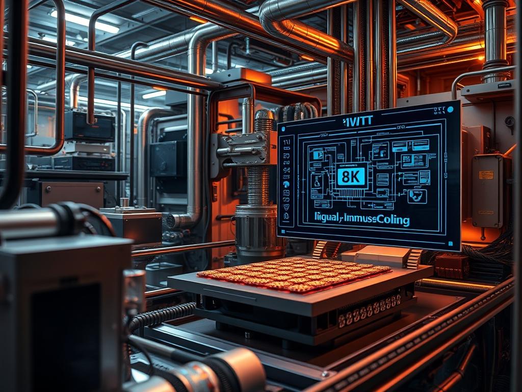
Liquid immersion cooling represents the terminal evolution of thermal management in high density computing environments. As traditional air cooling architectures encounter the physical limits of air heat capacity; liquid immersion cooling offers a high throughput alternative by submerging hardware in dielectric fluids. This method essentially eliminates the thermal resistance inherent in air-to-heatsink interfaces; it reduces the Power Usage Effectiveness (PUE) to near-unity levels. The primary problem addressed is the massive energy overhead of mechanical fans and compressor-based cooling units. By utilizing a fluid with high thermal inertia; systems can maintain stable operating temperatures even during peak computational bursts. This manual provides the architectural framework for single-phase immersion systems. It covers integration with real-time monitoring via Modbus and SNMP interfaces. It also details the hardware preparation required to transition from gaseous to liquid cooling mediums within a standard enterprise technical stack.
TECHNICAL SPECIFICATIONS
| Requirement | Default Port/Operating Range | Protocol/Standard | Impact Level (1-10) | Recommended Resources |
| :— | :— | :— | :— | :— |
| Dielectric Fluid | <10kV/mm Breakdown | ASTM D877 | 10 | Synthetic Hydrocarbon |
| Secondary Loop Flow | 15 - 35 GPM | ANSI/ASHRAE | 8 | Variable Frequency Drive |
| Monitoring Bus | TCP Port 502 / 161 | Modbus/SNMP | 7 | CAT6A Shielded |
| Pump Control | 0 - 10V DC | PWM / Analog | 9 | Industrial Logic Controller |
| Thermal Threshold | 35C - 55C Outlet | IEEE 1100-2005 | 9 | Stainless Heat Exchanger |
| OS Kernel Version | 5.15.0+ | Linux Thermal | 6 | lm-sensors / ipmitool |
THE CONFIGURATION PROTOCOL
Environment Prerequisites:
Installation requires strict adherence to the NEC 2023 for specialized electrical equipment and NFPA 70 for fire safety in data environments. All hardware must be validated for material compatibility; specifically; ensure that all PVC-jacketed cables are replaced with LSZH (Low Smoke Zero Halogen) or fluoropolymer variants to prevent plasticizer leaching. The system controller must have root or sudo permissions to access the I2C bus and execute commands via the sysfs interface. Hardware must be stripped of all mechanical fans; as the fluid viscosity provides excessive resistance that can burn out standard DC fan headers.
Section A: Implementation Logic:
The engineering design rests on the principle of convective heat transfer. Unlike air; which is an insulator; dielectric fluid acts as a high-efficiency transport medium. The implementation logic follows a “Total Encapsulation” strategy where the fluid absorbs energy directly from the CPU, GPU, and VRM components. This energy is then moved to a secondary liquid-to-liquid heat exchanger using a closed-loop pump system. The efficiency is governed by the Prandtl number of the fluid; essentially; the ratio of momentum diffusivity to thermal diffusivity. By bypassing the thermal bottleneck of a traditional air-shroud; the system achieves lower latency in thermal response times. This allows for higher computational density without the risk of thermal throttling.
Step-By-Step Execution
1. Component De-fan and Surface Prep
Remove all high-RPM fans from servers and power supplies. Clean all original thermal interface material (TIM) from the CPU and GPU using isopropanol 99%.
System Note: Removing fans prevents physical obstruction in the fluid and reduces the current draw on the 12V rail. This action must be logged in the BIOS/UEFI by disabling “Fan Speed Monitoring” to prevent a “System Halt” on boot. Use ipmitool sensor list to verify that the motherboard is not reporting false-positive hardware failures after fan removal.
2. Sensor Array Deployment
Install PT100 RTD or Type-K Thermocouples at the tank inlet and outlet manifolds. Secure these sensors to the industrial logic controller.
System Note: These sensors provide the raw data for the PID (Proportional-Integral-Derivative) loop. If the delta-T between the inlet and outlet exceeds 10C; the controller will automatically trigger an increase in pump throughput. Use cat /sys/class/thermal/thermal_zone*/temp to verify that the kernel is receiving valid telemetry.
3. Tank Saturation and Air Purge
Slowly inject the dielectric fluid into the tank until it covers the highest point of the DIMM modules by at least 50mm. Execute a low-speed pump cycle to purge air trapped under the BGA chips.
System Note: Trapped air creates localized hotspots that can cause signal-attenuation or physical damage. Monitor the systemctl status immersion-pump.service to ensure the motor is not cavitating. Cavitation is identified by erratic current spikes on the VFD readout.
4. Thermal Loop Initialization
Initialize the secondary cooling loop (water-side) and verify that the flow rate meets the minimum requirements established in the technical specifications table.
System Note: The heat exchanger is the primary site of energy transfer. If the secondary loop fails; the fluid will reach thermal equilibrium with the environment; leading to a rapid rise in thermal-inertia. Use fluke-multimeter probes to verify that the pump contactors are engaging according to the logic programmed in Step 2.
5. Logic Controller Configuration
Load the cooling management software onto the head node. Configure the iptables or ufw to allow traffic on Port 502 for Modbus communication.
System Note: Command: sudo ufw allow 502/tcp. This allows the central monitoring dashboard to scrape metrics from the sensors. This data is the payload for the efficiency analytics engine.
6. Sub-mersion Testing and Load Simulation
Power on the compute nodes and run a stress test using stress-ng or mprime to simulate a maximum payload.
System Note: Command: sudo stress-ng –cpu 0 –io 4 –vm 2 –vm-bytes 128M –timeout 60s. Observe the temperature rise curve. A healthy system should see the temperature stabilize within 15 minutes due to the high specific heat capacity of the dielectric fluid.
Section B: Dependency Fault-Lines:
The most frequent failure point is material degrading. Certain elastomers used in gaskets can swell when exposed to synthetic hydrocarbons; leading to seal failure. Another critical bottleneck is the “Siphon Effect” during maintenance; where fluid can travel through cable jackets via capillary action if not properly blocked with a drip loop. Furthermore; check for library conflicts in the python-pymodbus stack if using custom scripts for hardware control; as version mismatches can cause packet-loss in the sensor telemetry stream.
THE TROUBLESHOOTING MATRIX
Section C: Logs & Debugging:
When a thermal event occurs; the first point of inspection is the system log located at /var/log/thermal_manager.log. Look for error strings such as E-TEMP-CRIT or E-FLOW-LOW.
- Error Code E-THM-01 (Thermal Runaway): This indicates that the heat being generated exceeds the heat exchanger capacity. Check the secondary water loop for blockages or check the VFD for a tripped breaker. Use sensors to identify which specific CPU socket is overheating.
- Error Code E-FLUID-05 (Low Dielectric): This indicates a leak or fluid migration. Inspect the floor sensors and check the path /etc/immersion/sensors.conf to ensure the trip levels are set correctly.
- Log Verification: To view real-time data flow from the pump controller; use tail -f /var/log/syslog | grep “pump-speed”. If the throughput remains static while temperatures rise; the idempotent nature of the control script has been compromised by a logic hang.
OPTIMIZATION & HARDENING
Performance Tuning:
To maximize thermal efficiency; tune the PID coefficients (Kp, Ki, Kd) in the controller software. Reducing the “Proportional” gain can prevent pump oscillation; while increasing the “Integral” term ensures the system eliminates long-term steady-state errors in temperature. For systems with high concurrency; consider implementing a predictive cooling algorithm that ramps up pump speed based on the CPU load average found in /proc/loadavg rather than waiting for the temperature rise.
Security Hardening:
Physical security is paramount as the hardware is submerged. Ensure that the tank lid is integrated into the “Chassis Intrusion” header on the motherboard. From a network perspective; isolate the cooling management system on a dedicated VLAN. Use iptables to restrict access to the Modbus port to only the administrative IP range. Apply chmod 600 to all configuration files containing sensor calibration offsets to prevent unauthorized tampering.
Scaling Logic:
Scaling a liquid immersion cooling setup involves a modular “Manifold-First” design. Instead of individual heat exchangers for every tank; use a central “CDU” (Cooling Distribution Unit) that manages a primary loop. Use large-diameter stainless steel piping to reduce fluid latency and maintain constant pressure across multiple tanks. When adding new nodes; ensure the fluid level is recalculated to maintain the 50mm displacement buffer.
THE ADMIN DESK
How often should dielectric fluid be tested?
Perform an acidity and dielectric breakdown test every 12 months. Contamination from dust or component leaching can reduce the breakdown voltage. Use the ASTM D877 standard for field testing to ensure the fluid remains within safe operating parameters.
Can I use standard CAT6 cables in the tank?
No; standard PVC jackets will leach plasticizers into the fluid; making it cloudy and eventually brittle. You must use Teflon or LSZH (Low Smoke Zero Halogen) rated cables to maintain fluid integrity and prevent long-term signal-attenuation issues.
What is the “Drip-Safe” protocol?
When removing a server for maintenance; it must be suspended above the tank for 5 minutes. Use a specialized “Drip Tray” to capture runoff. Use a dielectric cleaner or isopropanol to remove residual fluid from the gold pins before re-insertion.
How do I clear a “Fan Failure” error on boot?
Access the BIOS/UEFI and set all fan headers to “Ignore” or “Disabled”. If the firmware does not allow this; you may need to install a “Fan Simulator” resistor (PWM-to-Fixed-Signal) on the motherboard headers to spoof a constant RPM signal.
What causes pump cavitation in immersion systems?
Cavitation typically occurs if the fluid viscosity increases due to low temperatures or if there is a restriction in the suction line. Ensure the fluid is pre-heated to at least 20C before initiating high-speed flow to maintain optimal throughput.

